British Telecom (BT) Test Cards
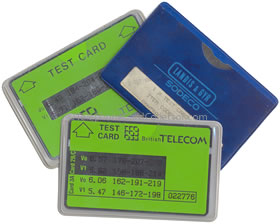 Test Cards were manufactured by Landis & Gyr to aid British Telecom (BT) engineers in Payphone Maintenance Centres (PMC) to repair mechanical and make electrical adjustments to the cardphone reader found within Landis & Gyr optical BT Phonecard operated payphones used in the field e.g. high street locations.
Read on to discover what sets Test Cards apart from other British Telecom Phonecards, including the closely associated British Telecom Service Card and how they were used.
Four types of BT Test Cards
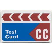
When most fusilatelists (telephone card collectors) think of British Telecom Test Cards they will think of the five or six different designs as illustrated in most UK Phonecard catalogue (BTT001-BTT006). However, in fact there were four different types of Test Cards at the disposal of British Telecom technicians and engineers, these were:
‣Card test no. 1A - Test Card
‣Card test no. 2A - Transit Card
‣Card test no. 3A - Gauge Card
‣Magnetic BT Test Card (for use with credit card reader, found on later optical cardphone models)
Click the links above to jump straight to the section on any particular Test Card type, or continue to scroll down to learn about each in Test Card turn.
Card test no. 1A - Test Card
Item code 334853
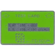
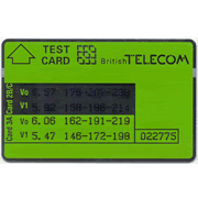
The Test Card 1A (pictured below) was the most commonly and widely used of the Test Card family. These special cards which were dimensionally accurate, and used as an optical reference for BT engineer servicing cardphone payphones, were solely for the purpose of diagnosing and aiding in the repair of optical cardphone card readers electrical faults and adjustments.
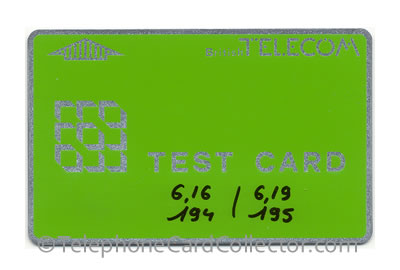
Pictured above - BTT001 - Green / Handwritten Control BT Test Card issued in March 1981.
BT Test Cards were issued in special protective wallets (normally transparent front, with light grey backing), these wallets helped to maintain the integrity and accuracy of the Test Cards optical track in diagnosing and assisting in adjustments to the cardreader.
It was essential that the Test Cards optical track be kept clean and free from scratches. The Test Card therefore needed to be handled by the edge away from the track and kept in its protective wallet when not in use. Erasures should never be made on a test card. In addition, and to help maintain the accuracy and the importance in the role of a Test Card, it was required that a Test Card must be replaced with a new Test Card 1A after it had been used on 30 occasions.
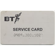
Uniquely, 1A Test Cards didn't include a value track or track of units, so telephone calls could not be made using one from the cardphone, therefore effectively you could never have a used Test Card, unlike with all other BT Phonecards, including the BT Service Card (which could be used to make calls - but only when the cardphone was opened for maintenance purposes).
BT Test Cards were used by British Telecom engineers in service centres for two different tests of optical Card Readers. These tests were - Test 10 and Test 11.
To view the full list of Card Reader tests or scroll down to 'Optical Card Reader Tests'.
Layout of a BT Phonecard
Before reading on and understanding the differences between the Test 10 and Test 11 and how the Test Card 1A was utilised, it's worth understanding a bit more about what lies beneath the surface of a Landis & Gyr optical BT Phonecard/Test Card.
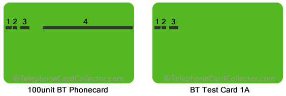
Pictured above - Standard BT Phonecard alongside a BT Test Card - Test Cards don't feature a 'value track'.
Each Phonecard stores information regarding its validity and value in an optical track (two tracks in the case of a 200/240 unit card). The optical track is in the form of a hologram which is called the family code. The track length (4) determines the value of the card.
The following additional information is included at the beginning of each optical track:
1. Mirror bit - a small piece of reflective material
2. Start bit - a piece of the hologram 5/8 of the width of the value unit
3. Type code - four out of seven value units
The following information is found on all BT Phonecards with the exception of the Test Card 1A:
4. Value track or track of units e.g. 100units
Notes: The mirror bit and the start bit are the same on every BT Phonecard.
The type code is a combination of four out of seven units; a different combination is used for each type of card for example user, service and so on.
Test Card 1A - Card Reader Tests 10 and 11
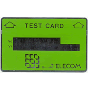
A Test Card 1A is shown below in its protective wallet, the figures for V0 (for example 6.49) and V1 (for example 5.71) first needed to be noted before starting tests 10 and 11.
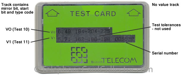
Pictured above - Test Card 1A explained.
Test 10 - V0
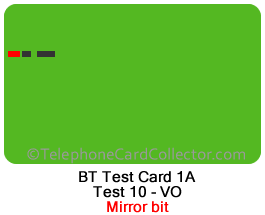 When performing Test 10, the Test Card 1A was used to check the optical Card Readers ability to read a phonecards 'mirror bit' as pictured right and highlighted in red. For explanation on a Phonecards 'mirror bit' please see 'Layout of a BT Phonecard' above.
To achieve this the BT engineer first needed to note the V0 value found on the front of the Test Card e.g. VO 6.49. The Test Card 1A was then inserted into the Card Reader slot with the black side towards the reading head, where it was automatically clamped in place. The BT engineer would then position the Card Readers reading head over the Test Cards 'mirror bit'.
Once the 'mirror bit' had been found, the engineer would then slowly turn the 'knurled knob' located on the side of the Card Reader to move the reading head over the whole of the Test Cards 'mirror bit', noting the maximum reading on the voltmeter.
If the optical cardphones Card Reader is operating correctly, the maximum reading should be equal to the value of VO e.g. 6.49 as shown on the front of the Test Card that's being used in the test.
If however, the VO value was higher or lower than that of the Test Card an adjust (coarse/fine) could then be made on the Card Readers analogue PCB (Printed Circuit Board). This adjustment would help to obtain the value VO indicated on the Test Card.
If the Test Cards VO value could not be obtained further tests including Test 3 and Test 10, Test 11 and Test 1 (see full test list below) could then be performed by the engineer to identify and correct the fault.
Test 11 - V1
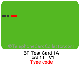 When performing Test 11, the Test Card 1A was used to check the optical Card Readers ability to read a phonecards 'type code' as pictured right and highlighted in red. For explanation on a Phonecards 'type code' please see 'Layout of a BT Phonecard' above.
To achieve this test the BT engineer first needed to note the V1 value found on the front of the Test Card e.g. V1 5.71. The Test Card was then inserted into the Card Reader slot with the black side towards the reading head.
Once the Test Card 1A was inserted into the Card Reader it was automatically clamped in place. The BT engineer would then position the Card Readers reading head over the Test Cards 'type code'.
Once the 'type code' had been found, the engineer would then slowly turn the 'knurled knob' located on the side of the Card Reader to move the reading head over the whole of the Test Cards 'type code', noting the maximum reading on the voltmeter.
If the optical cardphones Card Reader is operating correctly, the maximum reading should be equal to the value of V1 e.g. 5.71 as shown on the front of the Test Card that's being used in the test.
If however, the V1 value was higher or lower than that of the Test Card an adjustment could then be made on the Card Readers analogue PCB (Printed Circuit Board). This adjustment would help to obtain the value V1 indicated on the Test Card.
If the Test Cards V1 value could not be obtained Test 3 could then be performed by the engineer to identify and correct the fault.
British Telecom 1A Test Cards
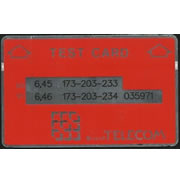
All of the different BT Test Cards 1A and their catalogue numbers e.g. BTT001 are shown below. To view a larger image simply click the picture of the card below.
Along with the 1A Test Cards shown above, it is also known that BT Test Cards were issued in four additional colours/shades, deep blue, light blue and two variations of yellow, these are shown below.

Pictured above - BT Test Cards aren't all green or red.
For more information relating to the above blue and yellow Test Cards, please visit Optical-Cards.com.
British Telecom Test Cards were issued in batches, it is known from Landis & Gyr that in excess of 41,000 BT Test Cards were issued between 1981 and 1995.
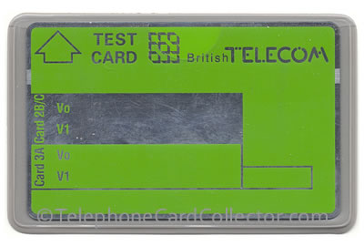
Pictured above - BTT005 - Blank BT Test Card with no numbers/values.
Optical Card Reader Tests
Summary of electrical tests for the Card Reader:
‣Test 1: Positioning the reading head track (requires Service Card)
‣Test 2: Setting the start position of the reading head (requires Service Card)
‣Test 3: Adjustment of the automatic power shut down (requires Service Card)
‣Test 4: Measure + 12V supply
‣Test 5: Measure - 12V supply
‣Test 6: Adjust + 5V supply
‣Test 7: Adjust motor current
‣Test 8: Measure motor phases
‣Test 9: Adjust digital to analogue converter
‣Test 10: Adjustment of order 0 (requires Test Card)
‣Test 11: Adjustment of order 1 (requires Test Card)
‣Test 12: Adjustment of motor position light gate
‣Test 13: Check maximum time to erase detector
‣Test 14: Check the erase head voltage
‣Test 15: Adjustment of erase head power
‣Test 16: Alignment of erase head to reading head (requires Service Card)
Card test no. 2A - Transit Card
Item code 334854
The Test Card 2A (transit card) was used to help make mechanical adjustments and corrections to the position of the Card Readers erase head.
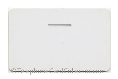
Pictured above - Card test no. 2A - Transit Card.
With the Test Card 2A inserted into the Card Readers slot, the BT engineer would check to ensure that the erase head was sitting squarely and centrally over the Test Card 2A when viewed directly from above. Adjustment could then be made as necessary to correct the position of the erase head if the alignment was out.
Card test no. 3A - Gauge Card
Item code 334914
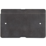
Like the Test Card 2A (transit card), the Test Card 3A (gauge card) was also used to make mechanical adjustments of the Card Reader.
The Card Test 3A was used in the adjustments of the Card Readers microswitches to help ensure that a Phonecard was locked in place, when inserted into the Card Reader slot.
While on the face of it the Test Card 3A resembled a simply piece of metal (pictured below right), it was in fact a high precison tool, which like the Test Card 1A needed to be handled with care and also was issued in a special protective wallet (pictured below left).
Pictured above - Card test no. 3A - Gauge Card.
To test that the Card Reader microswitches were working correctly, the Test Card 3A was inserted into the reader assembly until the front edge of the Test Card 3A touched the card presence microswitch operating lever.
With the Test Card 3A inserted into the Card Reader the BT engineer would then check:
1. The card presence microswitch was operating and moving to the correct position.
2. The microswitch was returning to its normal unoperated position when the Test Card 3A was withdrawn.
A single Test Card 3A was issued to each Payphone Maintenance Centres (PMC) across the UK.
Notes: According to records, the Test Card 3A should only be ordered if the PMC has not already got one.
BT Magnetic Test Cards
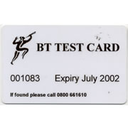
BT magnetic 'swipe' Test Cards such as the ones illustrated below were used by British Telecom engineers to test the credit card readers in BT payphones. To view a larger image simply click the picture of the card below. The front and reverse of each card is shown in the larger view.
Test Cards information and help
 The information above has been complied based on information found within the British Telecom 'Product Handbook Cardphone 1C and Cardphone 2A' issued in May 1989. It has been reported that a 'BT Test Card 2B' was also issued, however there is no reference to such a card within the 1989 Cardphone manual.
If you know different and can provide information, possibly a later issued Cardphone manual, please contact me so that I can update this webpage with new/further information.
In addition as a passionate Phonecard collector, I'm keen to collect all the different BT Test Cards along with other BT Phonecards that were commissioned and produced for British Telecom to maintain the cardphone payphone network. If you have any unwanted BT Test Cards to sell or giveway to me, I'd be very keen to hear from you. Please contact me via my contact page.
BT Test and Service Card Images - discover more on Pinterest
Follow Telephone Card Collector's board BT Test and Service Cards on Pinterest.Last updated: 2nd January 2026
Popular Pages
Collector Shop
Site Maps
TelephoneCardCollector.com © 2013-2026
Please do NOT copy any content without prior consent, thank you.


